Air Supply System Components Explained
What Does an Air Supply System Consist Of? Compressor, Receiver Tank, and FRL Explained at Once
-
04 Sep, 2025

-

What Does an Air Supply System Consist Of? Compressor, Receiver Tank, and FRL Explained at Once
Pneumatic Technology Explained · Air Supply Series
Let’s get straight to the conclusion: an air supply system is not just one compressor — it is an entire chain of “generation → storage → purification → pressure regulation → consumption”. The compressor generates the air, the receiver tank buffers and stabilizes pressure, the after-treatment equipment (filters, dryer, FRL) purifies and regulates, and only then does the air reach the cylinders and solenoid valves. If any link in the chain fails, the air at the point of use suffers.
The Air Supply System as One Chain
Generation and storage: the compressor compresses air to a set pressure (commonly 0.7–1.0 MPa in industry). The compression process carries in water vapor, oil mist, and particles. The receiver tank behind it buffers and stabilizes pressure, while also letting the hot compressed air cool down initially and separate out condensate.
Purification and regulation: filters remove particles and water, the dryer brings water vapor down to the target dew point, and the regulator stabilizes the output pressure. The FRL unit (filter–regulator–lubricator) is the most common treatment package at the point of use, and directly determines the quality and pressure of the air delivered to the actuators.
The Four Links of the Air Supply System
| Link | Generation | Storage | Purification | Regulation & use |
| Equipment | Air compressor | Receiver tank | Filters / dryer | FRL / regulator |
| Function | Compress air | Buffer and stabilize | Remove water, oil, particles | Regulate and supply |
| Typical problems | Insufficient air volume | Pressure fluctuation | Water and oil in air | Unstable pressure |
Field Notes: Mistakes We Have Seen
- Installing only a compressor with no after-treatment. The air is dirty and wet, and end components fail quickly.
- Sizing the receiver tank too small. Large pressure swings, and the pressure drops as soon as consumption rises.
- Installing only one filter. Particles, water, and oil need staged treatment — one filter is not enough.
- Ignoring the end-of-line FRL. However clean the supply air, unstable regulation at the point of use still means instability.
Frequently Asked Questions (FAQ)
Q1: What is the minimum an air supply system needs?
A system that supplies air reliably needs at least four parts: a compressor (generation), a receiver tank (buffering and stabilization), after-treatment (filter and dryer, to remove water, oil, and particles), and a regulation/supply unit (a regulator or an FRL unit). After-treatment is a matter of “class”: for modest requirements a filter alone may do; for high requirements add a dryer and an oil-removal filter. But the compressor, receiver tank, and pressure regulation are essentially non-negotiable. To judge what you are missing, look at the air-quality requirement at the point of use: the more precise and cleaner the application, the less you can skimp on after-treatment.
Q2: Is a receiver tank mandatory?
Strongly recommended. The tank’s job is not to “store some air as backup” but to buffer pressure and initially separate condensate. A compressor outputs intermittently or in pulses; with a tank, pressure fluctuation is smoothed out and pressure doesn’t sag at peak demand. At the same time, the hot compressed air cools in the tank and part of the water condenses out first, easing the load on after-treatment. Without a tank, pressure rises and falls, the compressor starts and stops frequently, and its life shortens. Size the tank to the compressor’s free air delivery — this link cannot be skipped.
Q3: What is the difference between an FRL unit and compressor after-treatment?
Different jobs, different locations. Compressor after-treatment (coarse filter, dryer, oil remover) performs bulk purification at the source, treating the whole plant’s air to a certain class. The FRL unit does fine adjustment at the point of use, close to the cylinders and valves — filtering residual particles and water, regulating pressure to what that equipment needs, and adding oil-mist lubrication as required. Think of it this way: after-treatment governs “overall quality”, the FRL governs “local precision and pressure”. Working together, they let end components get clean air at the right pressure.
Q4: What supply pressure should be set?
Industrial pneumatic systems commonly work at 0.6–0.8 MPa (about 6–8 bar); compressor outlets are usually set at 0.7–1.0 MPa to leave margin for line pressure drop. The actual setting depends on your air-consuming equipment: cylinders and valves each have a rated pressure range. Take the pressure requirement of the highest-demand point, add the line pressure drop (typically about 0.1 MPa), and that is the compressor setting. Higher is not better — every 0.1 MPa of extra pressure raises compressor energy consumption noticeably, so set it as needed and don’t turn it up blindly.
Q5: How do I judge whether the air supply system is adequate?
Watch two signals. First, pressure: does it drop noticeably at peak demand, or even below the equipment’s minimum requirement? A large drop means insufficient air volume or excessive pressure drop. Second, quality: do cylinders and valves stick, rust, or leak frequently? These usually mean excessive water, oil, or particles in the air. A simple approach: install a pressure gauge at the point of use to watch fluctuation, and check filter drainage and element condition. Stable pressure and healthy components mean the system is basically adequate; otherwise, troubleshoot segment by segment from air volume, pipe diameter, and after-treatment.
Conclusion
The air supply system is “one chain” — don’t stare only at the compressor. When generation, storage, purification, and regulation are all in place, the point of use gets stable air, and the components last.
Suggested Illustrations
- Air supply system flow diagram: compressor → receiver tank → filter → dryer → FRL → points of use, showing the chain visually.
- Four-link comparison chart: a four-quadrant graphic (generation / storage / purification / regulation) to pair with the table above.
The above content was compiled by the LEANYEE pneumatic technical team from hands-on commissioning experience, for reference by industry peers.
Technical Disclaimer
The fitting selection, thread types, and technical parameters discussed in this article are based on applicable international standards, including ISO 4414 (Pneumatic Fluid Power — General Rules and Safety Requirements), ISO 8573 (compressed air quality), ISO 6358 (flow characteristics), and relevant thread standards such as ISO 7-1, ISO 228-1, and ANSI/ASME B1.20.1, together with publicly available technical information from international manufacturers such as SMC, Festo, and Parker.
This article is intended for general technical reference only. Actual performance may be affected by cylinder bore size, load, operating pressure, temperature, piping layout, and other application-specific factors.
On-site testing and commissioning are recommended where necessary. Always refer to the product documentation and technical parameters confirmed by the manufacturer for the specific product being used.
LEANYEE Technical Team
Topic: Understanding the composition of the air supply system | Target readers: junior purchasing staff, maintenance newcomers, operators
More News & Insights
-
Leanyee
 29 Oct, 2026Pneumatics in Electronics CleanroomsPneumatics in Electronics and Semiconductor Cleanrooms: Cleanliness and ESD ProtectionRead Article
-
Leanyee
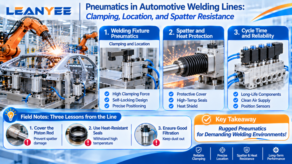 22 Oct, 2026Pneumatics in Automotive Welding LinesPneumatics in Automotive Welding Lines: Clamping, Location, and Spatter ResistanceRead Article
-
Leanyee
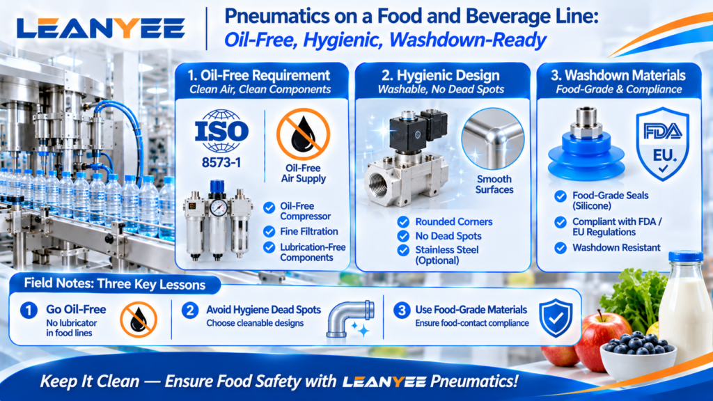 15 Oct, 2026Pneumatics for Food and Beverage LinesPneumatics on a Food and Beverage Line: Oil-Free, Hygienic, Washdown-ReadyRead Article