How to Choose a Solenoid Valve
How to Choose a Solenoid Valve: Orifice Size, Flow (Cv), Pressure, and Voltage Aligned in One Go
-
07 Apr, 2025

-

How to Choose a Solenoid Valve: Orifice Size, Flow (Cv), Pressure, and Voltage Aligned in One Go
Pneumatic Technology Explained · Solenoid Valve Series [Publication Date]
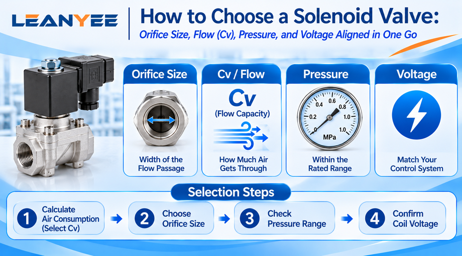
The short answer: selecting a solenoid valve is not a matter of “the port size looks about right.” Four parameters have to line up — orifice size, flow capacity (Cv/Kv), working pressure, and coil voltage. If any one of them is wrong, you end up with insufficient flow and slow actuation, leakage from over-pressure, or a burnt coil from the wrong voltage.
How Do the Four Parameters Line Up?
Orifice size sets how wide the flow passage is; flow capacity (Cv/Kv) sets how much air actually gets through. The two must match the cylinder’s air consumption. Working pressure must sit inside the valve’s rated range — too high and it leaks, too low and it will not shift. Coil voltage must match the control system, and DC 24 V is the industrial default.
Order of selection: start from the cylinder’s air consumption and required speed to establish Cv → then settle the orifice size → verify the pressure range → finally fix the coil voltage and port thread. ISO 6358 defines the method for determining flow characteristics, so the calculation can be done directly from Cv/Kv.
Aligning All Four Parameters, One by One
| Item | Orifice size | Cv (flow capacity) | Working pressure | Coil voltage |
| What it governs | Width of the flow passage | Actual flow capacity | Reliability of shifting | Electrical compatibility |
| Consequence of a mismatch | Insufficient flow | Slow actuation | Leakage / failure to shift | Burnt coil / no pull-in |
| What to check it against | Port thread size | Cylinder air consumption | Valve rated range | Control system power supply |
Field Notes: Mistakes We Have Seen
- Looking only at orifice size and ignoring Cv. Valves with the same port size can differ widely in Cv — flow capacity is the number that matters.
- Getting the voltage wrong. Wire a DC 24 V coil to AC 220 V, or the reverse, and the coil burns out in seconds.
- Running above the rated pressure. Over-pressure causes leakage and destroys the seals.
- Mismatching port threads. G, PT, and NPT look alike, but mixed assembly will leak.
Frequently Asked Questions (FAQ)
Q1: What are Cv and Kv, and how are they used? Both are flow coefficients that express a valve’s capacity. Cv is the US convention (1 Cv ≈ the flow of 1 US gallon of water per minute at a 1 psi pressure drop); Kv is the metric convention (1 Kv ≈ 1 m³ of water per hour at a 1 bar pressure drop). The two convert directly at roughly 1 Kv ≈ 1.16 Cv. When selecting, use Cv/Kv together with supply pressure and allowable pressure drop to estimate the flow the valve can pass, then compare that with cylinder air consumption to confirm there is enough flow and the speed target is met. ISO 6358 defines the standard method for determining the flow characteristics of pneumatic components, so selection can be worked out straight from the Cv/Kv figure published in the catalog.
Q2: How do I size the valve orifice from cylinder air consumption? First calculate the flow the cylinder needs (it depends on bore, stroke, speed, and cycle rate), then choose a valve with enough Cv, and finally read back the orifice size. The rough logic: a cylinder stroking quickly draws a high instantaneous flow, so the valve’s Cv must cover that peak with margin — otherwise supply cannot keep up and the speed falls short. In practice, engineers either use the manufacturer’s cylinder-to-valve matching table or step up one orifice size on experience. The point is never to let the valve become the flow bottleneck, and always to confirm against the flow data in the catalog.
Q3: How do I read a valve’s working pressure range? Every valve has a rated working pressure range (for example 0.15–1.0 MPa or 0–0.7 MPa), and your system pressure must fall inside it. Below the lower limit, a pilot-operated valve may fail to shift and a direct-acting valve may lack actuation force; above the upper limit, the valve leaks and the seals are damaged. Note that pilot-operated valves also carry a separate minimum pilot pressure requirement. So check both that system pressure sits within the valve’s range and that you have margin for fluctuation — do not run right at the limits.
Q4: How do I choose the coil voltage, and what is the difference between DC and AC? Follow the control system output; DC 24 V is the industrial standard. DC coils respond faster, have lower inrush, are safer, and generally last longer — they are the mainstream choice. AC coils (110 V / 220 V) draw a high inrush current and produce mains hum, and are now used far less. The critical rule is that the two must never be mixed: an AC coil wired to DC sees far lower impedance than rated, the current spikes, and the coil is destroyed; a DC coil wired to AC may fail to pull in reliably. Always verify that the coil nameplate matches the supply, use a relay as an interface where necessary, and never change the voltage just to save effort.
Q5: How do I tell G, PT, and NPT threads apart? These three pipe threads cannot be mixed. G is a parallel, non-sealing pipe thread to ISO 228-1 — straight thread, sealed by a gasket or face seal. PT is a 55° tapered pipe thread (Rc/Rp in ISO 7-1), sealed by the thread itself, usually with PTFE tape. NPT is a 60° tapered pipe thread to ANSI/ASME B1.20.1 (the US standard), also sealed on the thread. Thread angle and taper differ between them, so mixing causes leaks and can even damage the threads. Match the valve to the same thread standard as the fittings and piping, and confirm G, PT, or NPT before ordering — do not force them together on the assumption that “they are all pipe threads.”
Prepared by the LEANYEE pneumatics technical team based on hands-on commissioning experience, for reference by industry peers.
Technical Disclaimer
The fitting selection, thread types, and technical parameters discussed in this article are based on applicable international standards, including ISO 4414 (Pneumatic Fluid Power — General Rules and Safety Requirements), ISO 8573 (compressed air quality), ISO 6358 (flow characteristics), and relevant thread standards such as ISO 7-1, ISO 228-1, and ANSI/ASME B1.20.1, together with publicly available technical information from international manufacturers such as SMC, Festo, and Parker.
This article is intended for general technical reference only. Actual performance may be affected by cylinder bore size, load, operating pressure, temperature, piping layout, and other application-specific factors.
On-site testing and commissioning are recommended where necessary. Always refer to the product documentation and technical parameters confirmed by the manufacturer for the specific product being used.
LEANYEE Technical Team
More News & Insights
-
Leanyee
 29 Oct, 2026Pneumatics in Electronics CleanroomsPneumatics in Electronics and Semiconductor Cleanrooms: Cleanliness and ESD ProtectionRead Article
-
Leanyee
 22 Oct, 2026Pneumatics in Automotive Welding LinesPneumatics in Automotive Welding Lines: Clamping, Location, and Spatter ResistanceRead Article
-
Leanyee
 15 Oct, 2026Pneumatics for Food and Beverage LinesPneumatics on a Food and Beverage Line: Oil-Free, Hygienic, Washdown-ReadyRead Article