Overpressure Protection and Safety Valves
The "Safety Valves" in a Pneumatic System: Overpressure Protection Basics Explained at Once
-
08 Oct, 2026

-

The “Safety Valves” in a Pneumatic System: Overpressure Protection Basics Explained at Once
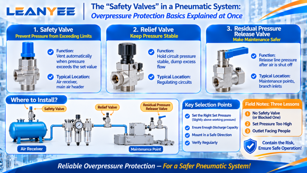
The most easily overlooked — and least dispensable — parts of a pneumatic system are the valves that relieve pressure. Once pressure runs away, at best components are damaged and lines burst; at worst people are hurt. This article covers the function and selection of three “safety valves”: the safety valve, the relief valve, and the residual pressure release valve.
1. The Several “Valves” of Overpressure Protection
| Valve | Function | Typical location |
| Safety valve | Vents automatically when pressure exceeds the set value | Air receiver, main air header, pressure vessels |
| Relief valve | Holds circuit pressure stable, dumping excess flow | Regulating circuits, pressure-stabilizing applications |
| Residual pressure release valve | Releases line pressure after the air is shut off | Maintenance points, branch inlets |
The safety valve is the last line of defence, preventing pressure from exceeding the rating of the equipment or vessel; the relief valve is the pressure stabilizer, keeping pressure steady; the residual pressure release valve is the vent that makes maintenance safe.
2. Where Overpressure Protection Is Required
Air receivers must have a safety valve (a mandatory requirement for pressure vessels). Downstream of the regulator on the main air header, and ahead of pressure-sensitive equipment, a safety valve or relief valve is often added as second-level protection. Every branch that needs air-off maintenance should have a residual pressure release valve.
3. Selection and Installation Points
Safety valve selection looks at the set pressure (slightly above the working pressure, below the vessel rating) and the discharge capacity (it must be able to vent the overpressure flow in time). Mount it with the outlet facing a safe direction, and verify it periodically to prevent seizing. The residual pressure release valve belongs at a maintenance point that is easy to reach.
(A quick selection reference for pneumatic safety valves will be available for download once the LEANYEE website launches.)
Field Notes: Three Lessons from the Line
- No safety valve on the receiver, or a blocked one — the pressure vessel loses its last line of defence, which is extremely high risk. Verify it on schedule.
- Safety valve set pressure too high — it does not act even when overpressure occurs. Set it below the vessel rating.
- Outlet facing people — the high-velocity discharge during venting injures. Point the outlet in a safe direction.
Conclusion
The safety valve, the relief valve, and the residual pressure release valve — three pressure-relief valves hold the pressure safety of a pneumatic system. Set the right pressure, mount them in the right place, and verify them on schedule, and the risk of runaway pressure is genuinely contained.
Suggested Illustrations
- Structure and symbol comparison of the safety valve, relief valve, and residual pressure release valve.
- Installation locations: safety valve on an air receiver, relief valve in a regulating circuit.
- Set pressure and discharge behaviour of a safety valve.
The above content was compiled by the LEANYEE pneumatic technical team from hands-on commissioning experience, for reference by industry peers.
Technical Disclaimer
The fitting selection, thread types, and technical parameters discussed in this article are based on applicable international standards, including ISO 4414 (Pneumatic Fluid Power — General Rules and Safety Requirements), ISO 8573 (compressed air quality), ISO 6358 (flow characteristics), and relevant thread standards such as ISO 7-1, ISO 228-1, and ANSI/ASME B1.20.1, together with publicly available technical information from international manufacturers such as SMC, Festo, and Parker.
This article is intended for general technical reference only. Actual performance may be affected by cylinder bore size, load, operating pressure, temperature, piping layout, and other application-specific factors.
On-site testing and commissioning are recommended where necessary. Always refer to the product documentation and technical parameters confirmed by the manufacturer for the specific product being used.
LEANYEE Technical Team
More News & Insights
-
Leanyee
 29 Oct, 2026Pneumatics in Electronics CleanroomsPneumatics in Electronics and Semiconductor Cleanrooms: Cleanliness and ESD ProtectionRead Article
-
Leanyee
 22 Oct, 2026Pneumatics in Automotive Welding LinesPneumatics in Automotive Welding Lines: Clamping, Location, and Spatter ResistanceRead Article
-
Leanyee
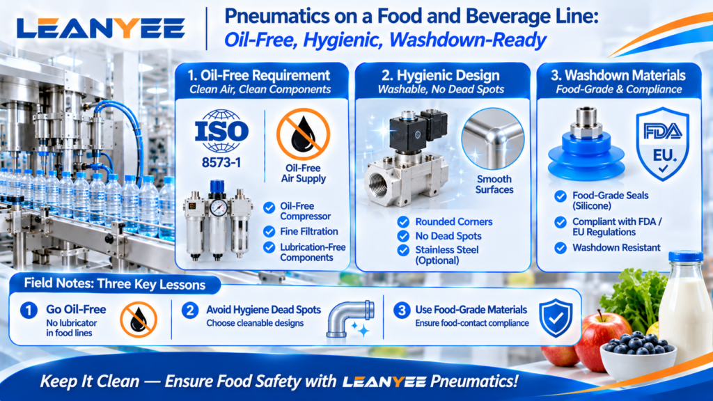 15 Oct, 2026Pneumatics for Food and Beverage LinesPneumatics on a Food and Beverage Line: Oil-Free, Hygienic, Washdown-ReadyRead Article