How to Read Pneumatic Symbols
Reading Pneumatic Symbols on Solenoid Valves: What 2/2, 3/2, 5/2, and 5/3 Actually Mean
-
27 Mar, 2025

-

Reading Pneumatic Symbols on Solenoid Valves: What 2/2, 3/2, 5/2, and 5/3 Actually Mean
Pneumatic Technology Explained · Solenoid Valve Series
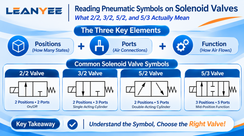
The short answer: pneumatic symbols are the “language of the drawing” — once you can read them, you can pick the right valve and connect the right ports. Everything comes down to three elements: positions (how many working states), ports (how many air connections), and function (how the air flows in each position). Master these three, and no symbol will ever look intimidating.
The Three Elements of a Symbol: Positions, Ports, Function
Positions are drawn as boxes — the number of boxes is the number of positions. Ports are the air connections, labeled with letters and numbers: P for pressure (supply), A/B for working (output) ports, R/S for exhaust. So 2/2 means two positions, two ports, and 5/2 means two positions, five ports. Arrows inside a box show the flow paths of that position, and the symbol ⊥ means the port is blocked (closed).
Normally open / normally closed is judged from the box on the spring-return side, i.e., the de-energized state. In a 5/3 valve, the center box shows the mid-position function — what happens when both coils are de-energized. The reading order for any symbol: count the positions first, then the ports, and finally see how the air paths connect in each position.
How to Read Common Symbols
| Symbol | Positions | Ports | Typical Use |
| 2/2 | 2 | 2 | On/off / shut-off |
| 3/2 | 2 | 3 | Single-acting cylinder |
| 5/2 | 2 | 5 | Double-acting cylinder |
| 5/3 | 3 | 5 | Mid-stop / pressure holding |
Field Notes: Mistakes We Have Seen
- Mixing up “positions” and “ports.” 2/2 is two positions, two ports — read it in that order. Count wrong, pick the wrong valve.
- Looking only at the model number, not the symbol. Two valves can both be “5/2” yet have different functions — always confirm against the symbol.
- Misreading normally open vs. normally closed. The de-energized state is the box on the spring-return side; don’t judge it from the energized box.
- Overlooking the mid-position function. In a 5/3 valve, the center box determines what the cylinder does when power is lost — check it before you order.
Frequently Asked Questions (FAQ)
Q1: How do I read a pneumatic symbol quickly? Three steps. First count the positions — the number of boxes: two boxes = two positions, three boxes = three positions. Then count the ports — the total air connections, i.e., the lines attached to the outside of the symbol. Finally read the function — the arrows and blocking marks inside each box: arrows show which ports are connected in that position, and ⊥ means the port is blocked. Take a 5/2 valve: two boxes (two positions), five ports (P, A, B, R1, R2); in the energized box P→A and B→R2 are connected, and in the de-energized box P→B and A→R1 are connected. Read symbols in this order and you won’t go wrong.
Q2: What are ports P, A, B, R, and S? These are the standard port labels: P is the pressure port (connect the air supply); A and B are the two working ports (connect the two chambers of the cylinder — A usually corresponds to extend, B to retract); R or S are the exhaust ports (connect a silencer or vent to atmosphere), sometimes labeled R1/R2 or S/R. A five-port valve is simply P, A, B plus two exhausts. Keep these letters straight and you’ll never plumb a valve wrong: air supply into P, cylinder to A/B, exhaust to R/S. Labeling varies slightly between brands — follow the datasheet.
Q3: How do I tell normally open from normally closed on a symbol? Look at the box on the spring-return (de-energized) side. Normally closed (NC) means the air path is blocked with ⊥ when de-energized; normally open (NO) means the path is drawn as an arrow, i.e., flowing, when de-energized. How to judge: find the spring-side box and see whether P connects to the working port by an arrow (open) or a block (closed) — open means NO, closed means NC. Note that “normally” refers to the de-energized default state, not the energized one — this is exactly where most people read it backwards. Find the spring side first, then judge.
Q4: What does the center box of a 5/3 valve mean? A 5/3 valve has three boxes, and the middle one shows the mid-position state — what happens when both coils are de-energized, i.e., the power-off default. The drawing in the center box determines how the cylinder stops when power is lost: if both A and B are blocked (closed center), the cylinder holds its position with pressure locked; if both A and B are exhausted (exhaust center), the cylinder depressurizes and can be moved freely; if both A and B are supplied with air (pressure center), both sides are pressurized and the piston is locked. The center box is therefore the single most important checkpoint when selecting a 5/3 valve — it defines your power-off safety strategy.
Q5: Why “read the symbol first, then the model number”? Because model numbers follow each manufacturer’s own naming rules — the same function can carry completely different model numbers across brands, while the symbol is an internationally standardized graphic language that shows the valve’s true function directly. Choosing by model number alone invites errors caused by naming differences; choosing by symbol tells you exactly whether the positions, ports, and function meet your needs. The correct sequence: first understand the symbol you need (how many ports and positions, NO or NC, what mid-position function), then compare candidate model numbers against it, and finally confirm with the datasheet. The symbol is the “requirement,” the model is the “implementation” — define the requirement first, then choose the implementation.
Prepared by the LEANYEE pneumatics technical team based on hands-on commissioning experience, for reference by industry peers.
The parameters and recommendations above are based on current international standards (ISO 5599-1 mounting surfaces for five-port directional control valves, ISO 15407-1 18/26 mm mounting surfaces, ISO 4414 general rules and safety requirements for pneumatic systems, ISO 6358 flow characteristics, ISO 8573 compressed-air quality, ISO 7-1 / ISO 228-1 pipe threads, IEC 60529 ingress protection) and public technical documentation from international manufacturers such as SMC, Festo, Parker, and Norgren. They are for reference only; actual performance depends on flow, pressure, voltage, media, temperature, and other factors. On-site commissioning is recommended, and the product datasheet and manufacturer-confirmed specifications shall prevail.
Technical Disclaimer
The fitting selection, thread types, and technical parameters discussed in this article are based on applicable international standards, including ISO 4414 (Pneumatic Fluid Power — General Rules and Safety Requirements), ISO 8573 (compressed air quality), ISO 6358 (flow characteristics), and relevant thread standards such as ISO 7-1, ISO 228-1, and ANSI/ASME B1.20.1, together with publicly available technical information from international manufacturers such as SMC, Festo, and Parker.
This article is intended for general technical reference only. Actual performance may be affected by cylinder bore size, load, operating pressure, temperature, piping layout, and other application-specific factors.
On-site testing and commissioning are recommended where necessary. Always refer to the product documentation and technical parameters confirmed by the manufacturer for the specific product being used.
LEANYEE Technical Team
More News & Insights
-
Leanyee
 29 Oct, 2026Pneumatics in Electronics CleanroomsPneumatics in Electronics and Semiconductor Cleanrooms: Cleanliness and ESD ProtectionRead Article
-
Leanyee
 22 Oct, 2026Pneumatics in Automotive Welding LinesPneumatics in Automotive Welding Lines: Clamping, Location, and Spatter ResistanceRead Article
-
Leanyee
 15 Oct, 2026Pneumatics for Food and Beverage LinesPneumatics on a Food and Beverage Line: Oil-Free, Hygienic, Washdown-ReadyRead Article