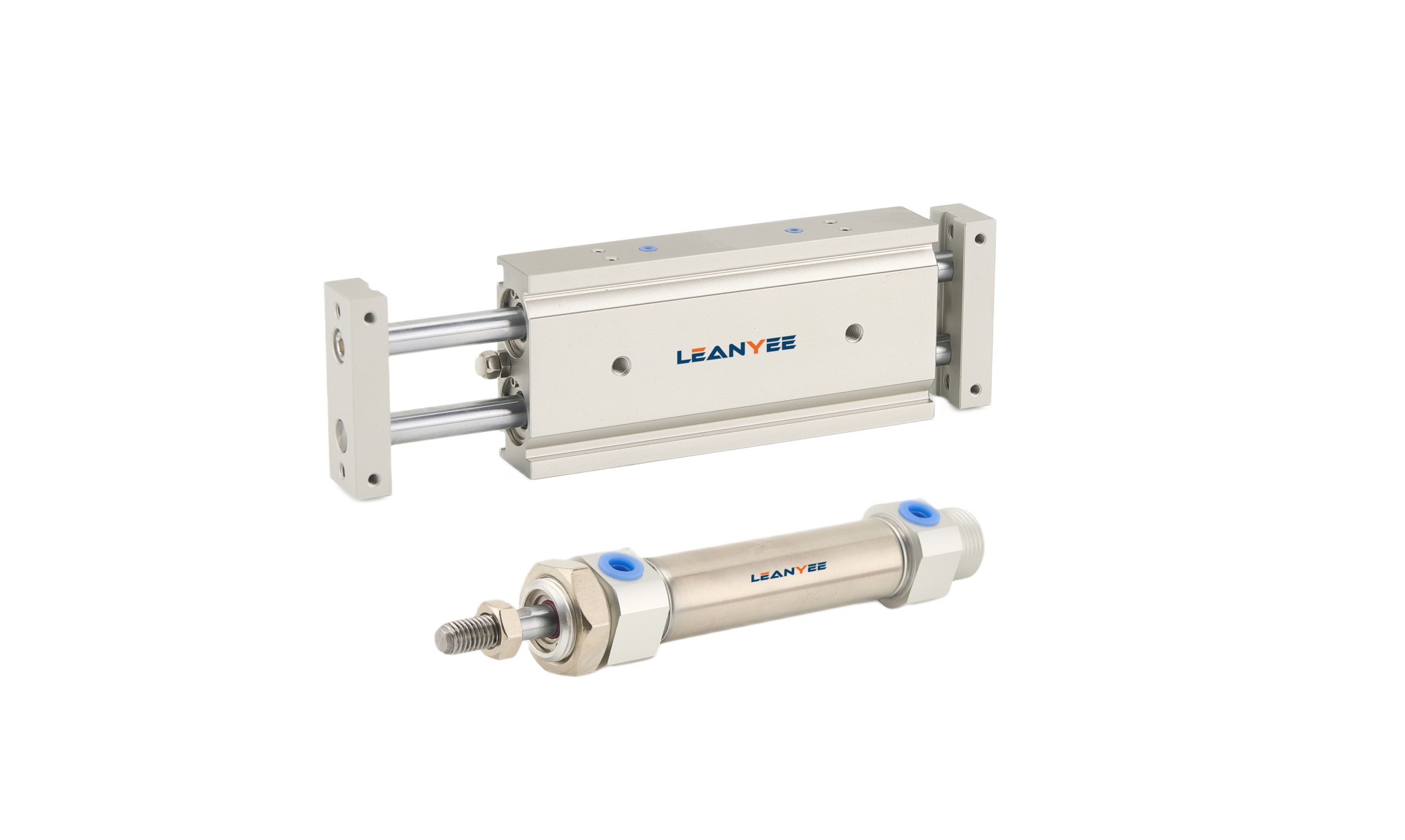
Three Ways to Use a Flow Sensor
Three Ways to Use a Flow Sensor in Pneumatics
-
03 Aug, 2026

-

Three Ways to Use a Flow Sensor in Pneumatics
Pressure is easy to measure, flow is hard — yet flow is exactly what exposes the hidden waste and hidden faults in a pneumatic system. A flow sensor has three typical roles in pneumatics, running from “is there any air at all” to “how much air did we spend”, each adding a layer of value.
1. Flow Switches and Flow Meters
First, separate the two: a flow switch is a switching device that triggers when flow reaches or falls below a set point, used to judge “is there air, is there enough air”; a flow meter outputs a live flow value for metering and logging. Both come in thermal and vortex designs, and in pneumatics the thermal flow meter is the most common.
2. Use One: Instantaneous Flow Monitoring
Monitor the air consumption of a branch or a machine in real time and judge whether it sits in the normal band. A sudden flow anomaly usually means a leak, a failed component, or a changed process — which makes online early warning possible.
3. Use Two: Leak Detection
Measure flow with the machine stopped: it should be close to zero. If flow continues, there is a leak. A flow meter quantifies the leak, which is more accurate than listening for it, and gives leak management a data basis.
4. Use Three: Energy Metering
Compressed air is expensive energy. Meter consumption by machine and by production line and pneumatic costs become visible: you can find the high-consumption areas and back up energy-saving projects and cost allocation with data. (A flow meter selection and energy-accounting reference will be available for download once the LEANYEE website launches.)
Field Notes: Three Lessons from the Line
- Using a flow switch instead of a flow meter for metering — a switching output has no value. Metering requires a flow meter.
- Flow meter installed where the flow pulses — the reading jumps. Install it in a straight, stable section of pipe.
- Range and pressure ignored — running over range or at the wrong pressure causes large errors. Match the selection to the actual duty.
Conclusion
The value of a flow sensor builds layer by layer, from “watching the air” to “finding the leaks” to “doing the accounts”. To manage pneumatic energy consumption and get leaks under control, a flow meter is a tool you cannot work around.
Suggested Illustrations
- Comparison of the output signals from a flow switch and a flow meter.
- Measuring flow with the machine stopped to identify a leak.
- An energy dashboard metering air consumption by machine and by line.
The above content was compiled by the LEANYEE pneumatic technical team from hands-on commissioning experience, for reference by industry peers.
Technical Disclaimer
The fitting selection, thread types, and technical parameters discussed in this article are based on applicable international standards, including ISO 4414 (Pneumatic Fluid Power — General Rules and Safety Requirements), ISO 8573 (compressed air quality), ISO 6358 (flow characteristics), and relevant thread standards such as ISO 7-1, ISO 228-1, and ANSI/ASME B1.20.1, together with publicly available technical information from international manufacturers such as SMC, Festo, and Parker.
This article is intended for general technical reference only. Actual performance may be affected by cylinder bore size, load, operating pressure, temperature, piping layout, and other application-specific factors.
On-site testing and commissioning are recommended where necessary. Always refer to the product documentation and technical parameters confirmed by the manufacturer for the specific product being used.
LEANYEE Technical Team
More News & Insights
-
Leanyee
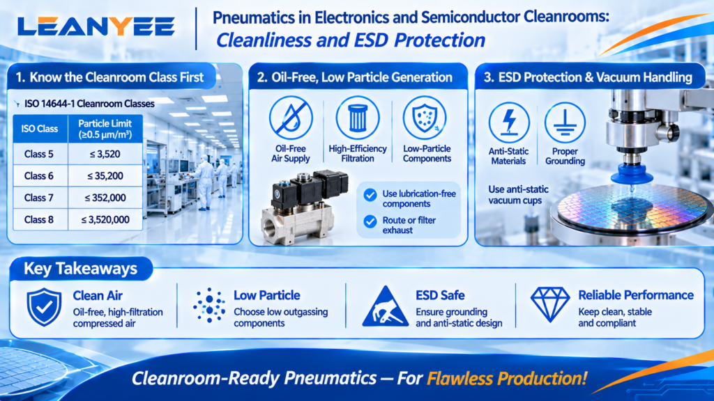 29 Oct, 2026Pneumatics in Electronics CleanroomsPneumatics in Electronics and Semiconductor Cleanrooms: Cleanliness and ESD ProtectionRead Article
-
Leanyee
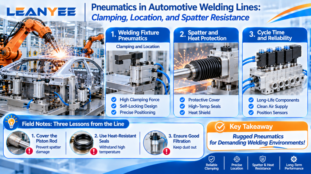 22 Oct, 2026Pneumatics in Automotive Welding LinesPneumatics in Automotive Welding Lines: Clamping, Location, and Spatter ResistanceRead Article
-
Leanyee
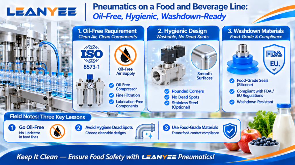 15 Oct, 2026Pneumatics for Food and Beverage LinesPneumatics on a Food and Beverage Line: Oil-Free, Hygienic, Washdown-ReadyRead Article