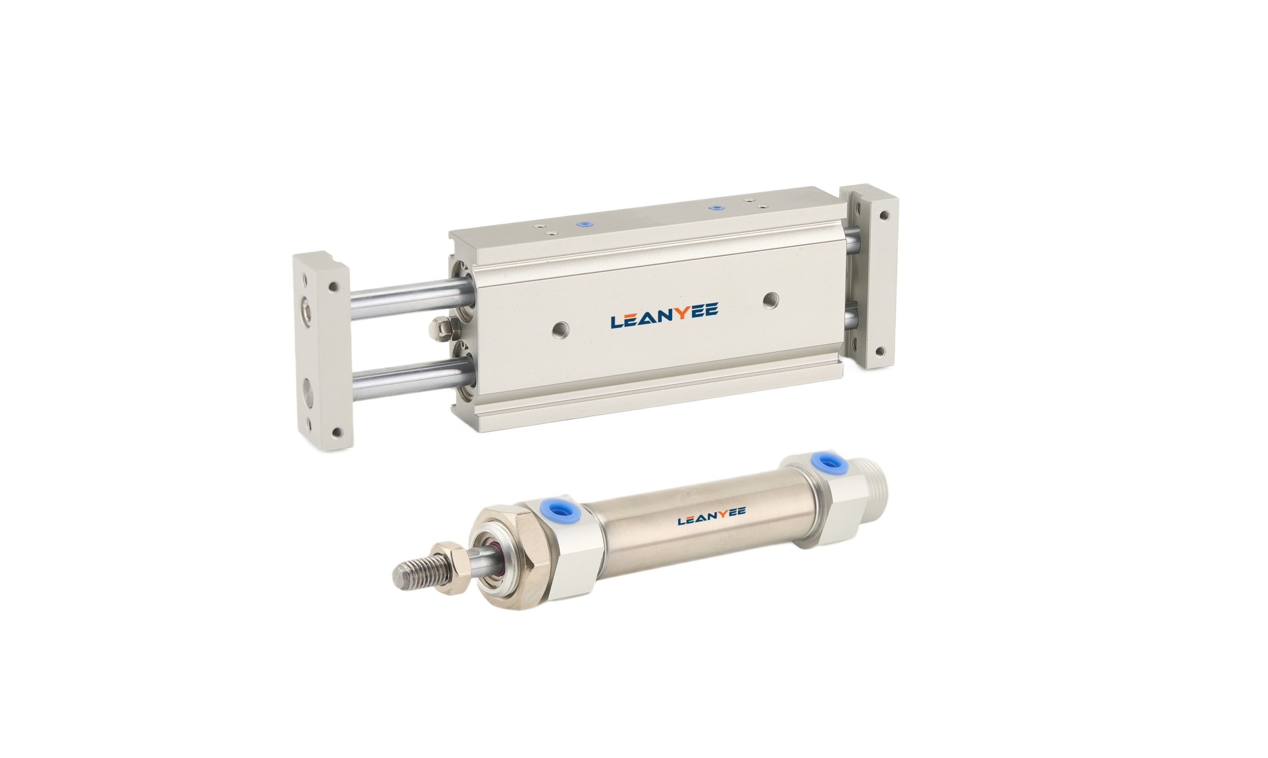
Throttle Valve vs Speed Control Valve
Throttle Valve vs Speed Control Valve: The Three Variables That Decide Cylinder Speed
-
08 May, 2026

-

Throttle Valve vs Speed Control Valve: The Three Variables That Decide Cylinder Speed
A cylinder runs fast and then slow, and slows further as soon as the load gets heavier — most people reach for the pressure regulator first, but the real question is “throttle valve or speed control valve”. Both control flow, yet one is at the mercy of load and the other compensates to hold speed steady. This article explains the difference, and the three variables that actually set the speed.
1. Throttle Valve: Simple Restriction, Drifting Speed
A throttle valve limits flow by shrinking the flow area — simple in construction, but its flow changes with load: a heavier load raises the differential pressure, the flow changes, and the speed goes with it. A plain throttle valve is fine where the load is steady and speed accuracy is undemanding; when the load varies, the speed drifts.
2. Speed Control Valve: Pressure-Compensated, Steady Speed
A speed control valve (a pressure-compensated flow control valve) adds a compensating element to the throttle. It automatically offsets the differential-pressure swings that load changes create, so flow stays essentially constant and cylinder speed stays steady. Where the load varies and speed must be stable, the speed control valve is the more reliable choice.
| Aspect | Throttle valve | Speed control valve |
| Construction | Simple | Includes pressure compensation, more complex |
| Speed stability | Strongly affected by load | Stable under load variation |
| Cost | Low | Higher |
| Best for | Steady load, modest requirement | Varying load, stability required |
3. Three Variables That Set the Speed: Flow, Differential Pressure, Throttle Position
Cylinder speed ultimately comes down to three things: flow (the valve’s capacity, which can be characterized by ISO 6358 flow characteristics), differential pressure (the greater the pressure difference across the valve, the faster the flow), and throttle position (meter-in vs meter-out). Meter-out is smoother than meter-in because back pressure builds on the exhaust side and steadies the motion — which is why speed-control circuits almost always meter out.
The right order for controlling speed: choose the throttle position first (meter-out), then decide between a throttle valve and a speed control valve according to how much the load varies, and finally match the orifice to the flow characteristics.
Field Notes: Three Lessons from the Line
- Speed changes whenever the load changes, and all you do is adjust the air pressure — that treats the symptom. Switch to a pressure-compensated speed control valve.
- Meter-in used in place of meter-out — the cylinder nods and stick-slips. Meter-out should be the default for speed control.
- Orifice chosen too small — a flow bottleneck caps the speed. Match the orifice to the ISO 6358 flow characteristics.
Conclusion
When speed is unstable, first decide whether the problem lies in the throttle position or the valve type: meter out first, use a speed control valve where the load varies, and match the orifice to the flow characteristics last. Line up the three variables and the cylinder speed settles down.
Suggested Illustrations
- Structural comparison of the throttle valve and the speed control valve (with and without pressure compensation).
- Speed characteristics of meter-in versus meter-out.
- Flow-versus-differential-pressure curves for the throttle valve and the speed control valve.
The above content was compiled by the LEANYEE pneumatic technical team from hands-on commissioning experience, for reference by industry peers.
Technical Disclaimer
The fitting selection, thread types, and technical parameters discussed in this article are based on applicable international standards, including ISO 4414 (Pneumatic Fluid Power — General Rules and Safety Requirements), ISO 8573 (compressed air quality), ISO 6358 (flow characteristics), and relevant thread standards such as ISO 7-1, ISO 228-1, and ANSI/ASME B1.20.1, together with publicly available technical information from international manufacturers such as SMC, Festo, and Parker.
This article is intended for general technical reference only. Actual performance may be affected by cylinder bore size, load, operating pressure, temperature, piping layout, and other application-specific factors.
On-site testing and commissioning are recommended where necessary. Always refer to the product documentation and technical parameters confirmed by the manufacturer for the specific product being used.
LEANYEE Technical Team
More News & Insights
-
Leanyee
 29 Oct, 2026Pneumatics in Electronics CleanroomsPneumatics in Electronics and Semiconductor Cleanrooms: Cleanliness and ESD ProtectionRead Article
-
Leanyee
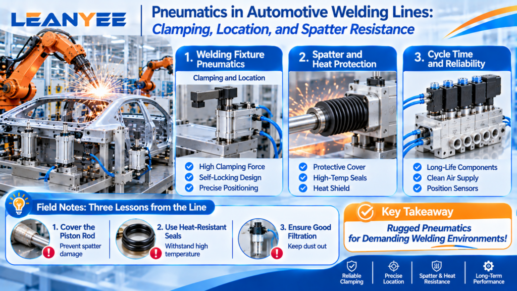 22 Oct, 2026Pneumatics in Automotive Welding LinesPneumatics in Automotive Welding Lines: Clamping, Location, and Spatter ResistanceRead Article
-
Leanyee
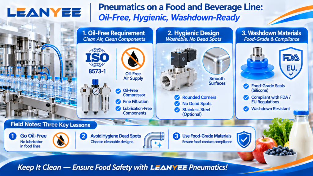 15 Oct, 2026Pneumatics for Food and Beverage LinesPneumatics on a Food and Beverage Line: Oil-Free, Hygienic, Washdown-ReadyRead Article