Valve Manifolds, Fieldbus, and IO-Link
Valve Manifolds, Fieldbus, and IO-Link: Where Solenoid Valves Are Heading
-
05 Jun, 2025

-

Valve Manifolds, Fieldbus, and IO-Link: Where Solenoid Valves Are Heading
Pneumatic Technology Explained · Solenoid Valve Series
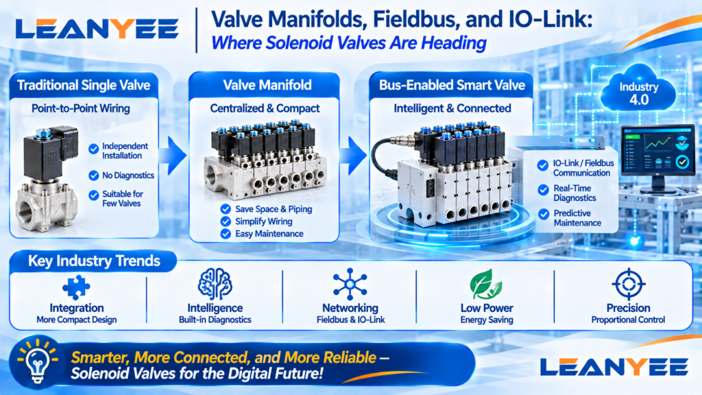
The short answer: the solenoid valve is not going away — it is moving toward “integration plus intelligence.” A valve manifold concentrates a bank of valves on one common air and electrical base; a fieldbus (IO-Link, industrial fieldbus) replaces a mass of point-to-point wiring with a single communication line; and with low-power coils and smart diagnostics, the valve changes from a “silent actuator” into a smart unit that can sense, connect, and predict.
From Single Valves to Manifolds, From Point Wiring to Bus
Valve manifold: multiple valves are mounted together on a base plate with integrated air channels and electrical interfaces. It saves space, cuts piping and wiring, and makes installation and maintenance far more efficient — ideal for machines with many valves.
Fieldbus and IO-Link: a communication bus replaces point-by-point I/O wiring, and IO-Link adds two-way transfer of diagnostic data (coil current, spool position, life prediction), enabling condition monitoring and predictive maintenance.
Traditional Single Valve vs. Manifold vs. Bus-Enabled Smart Valve
| Item | Traditional single valve | Valve manifold | Bus-enabled smart valve |
| Wiring | Point-to-point | Centralized base plate | Communication bus |
| Diagnostics | None | Limited | Condition / life prediction |
| Best suited to | Few, scattered valves | Many, concentrated valves | Smart production lines |
Field Notes: Mistakes We Have Seen
- Installing a manifold even for a handful of valves. With only a few valves, a manifold is simply not worth it.
- Ignoring fieldbus protocol compatibility. IO-Link, Profibus, EtherCAT — the choice must be right.
- Buying a manifold but using no diagnostics. Half the value of a manifold is in its diagnostics — do not waste it.
- Chasing intelligence for its own sake. Work out whether you need the data first, then decide on smart valves.
Frequently Asked Questions (FAQ)
Q1: What advantages does a valve manifold have over individual valves? A manifold mounts many solenoid valves on a single base plate with integrated air channels and electrical interfaces, and the advantages are clear. First, it saves space and piping: the valves share one supply and one exhaust instead of running a tube to each valve. Second, it saves wiring: a single, centralized electrical interface makes installation fast. Third, maintenance is easier — a faulty valve can be swapped individually in seconds. Fourth, expansion is simple: adding a valve just means adding a position on the base plate. The price is a slightly higher initial cost, and with few valves it is not worthwhile. So manifolds shine on automation equipment with many, concentrated valves — robot cells, packaging machines, special-purpose machines — while scattered, low-count installations are more economical with individual valves.
Q2: What is IO-Link, and what can it do? IO-Link is a point-to-point industrial communication protocol that connects sensors and actuators to the controller over a standard three-wire cable, carrying both control signals and two-way data. For solenoid valves, IO-Link can return diagnostic data such as coil current, spool position, cycle count, temperature, and remaining-life estimates, enabling condition monitoring, early fault warning, and predictive maintenance. It also allows parameters to be configured remotely, cutting downtime during changeover. Compared with traditional digital I/O it adds a “data channel,” and it is the key technology that makes valve manifolds and smart valves diagnosable — its adoption on factory floors keeps growing.
Q3: Which applications suit a valve manifold? Applications with many valves (generally 4–8 or more), concentrated layout, and frequent expansion or maintenance — robot cells, packaging machines, special-purpose machines, assembly lines. In these cases a manifold dramatically reduces piping and wiring, saves installation space and labor, and simplifies maintenance. Conversely, with only two or three valves scattered around a machine, a manifold adds cost and complexity — individual valves plus a terminal block are simpler. The rule of thumb: many valves, concentrated, space- and wiring-sensitive → manifold; few valves, scattered, simplicity first → individual valves.
Q4: How do I choose the protocol for a bus-enabled manifold? Start from the protocols your control system supports, then choose the manifold. Mainstream fieldbuses include Profibus, Profinet, EtherCAT, EtherNet/IP, and CC-Link, plus point-to-point protocols such as IO-Link. Points to weigh: first, match the brand and protocol of the PLC or master controller — never pick a protocol the controller does not support; second, consider speed and real-time behavior — motion control applications suit real-time buses such as EtherCAT; third, consider scalability and diagnostic capability. The principle is “follow the control system”: fix the master controller first, then the manifold’s communication protocol, and compatibility problems disappear.
Q5: Where are solenoid valves heading? Several directions. Integration: manifolds and multi-valve base plates keep getting more compact, combining air and electronics in one unit. Intelligence: built-in sensors and diagnostics return coil current, spool position, and life data for predictive maintenance. Networking: IO-Link and fieldbus spread, turning valves into addressable, configurable smart nodes. Low power: low-power coils cut heat and energy consumption. Precision: proportional valves and servo valves make flow and pressure continuously adjustable. The overall trend is the solenoid valve’s evolution from a “silent actuator” into a smart unit that can sense, connect, and predict — merging deeply with the digitalization of automated production lines.
Prepared by the LEANYEE pneumatics technical team based on hands-on commissioning experience, for reference by industry peers.
Technical Disclaimer
The fitting selection, thread types, and technical parameters discussed in this article are based on applicable international standards, including ISO 4414 (Pneumatic Fluid Power — General Rules and Safety Requirements), ISO 8573 (compressed air quality), ISO 6358 (flow characteristics), and relevant thread standards such as ISO 7-1, ISO 228-1, and ANSI/ASME B1.20.1, together with publicly available technical information from international manufacturers such as SMC, Festo, and Parker.
This article is intended for general technical reference only. Actual performance may be affected by cylinder bore size, load, operating pressure, temperature, piping layout, and other application-specific factors.
On-site testing and commissioning are recommended where necessary. Always refer to the product documentation and technical parameters confirmed by the manufacturer for the specific product being used.
LEANYEE Technical Team
| [Topic] Intelligence and industry trends | [Intended readers] Technical management, R&D, and decision makers |
More News & Insights
-
Leanyee
 29 Oct, 2026Pneumatics in Electronics CleanroomsPneumatics in Electronics and Semiconductor Cleanrooms: Cleanliness and ESD ProtectionRead Article
-
Leanyee
 22 Oct, 2026Pneumatics in Automotive Welding LinesPneumatics in Automotive Welding Lines: Clamping, Location, and Spatter ResistanceRead Article
-
Leanyee
 15 Oct, 2026Pneumatics for Food and Beverage LinesPneumatics on a Food and Beverage Line: Oil-Free, Hygienic, Washdown-ReadyRead Article